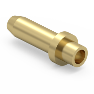
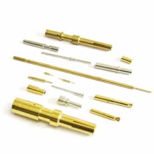
High-Strength Swage Terminal Pins for Secure Wire-to-Board Assemblies
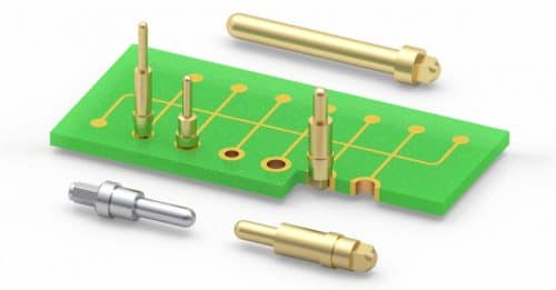
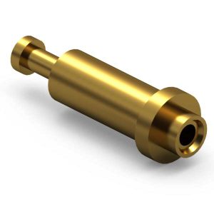
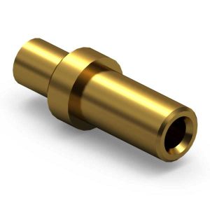
We engineer precision-machined Swage Terminal Pins designed for high-reliability wire-to-board architectures, PCB standoffs, and dynamic test points. Our high-speed turning matrix utilizes high-quality brass alloys subjected to specialized annealing heat treatments, reducing the risk of cracking during the mechanical swaging process. Furthermore, our test data shows superior pull-out strength once the pin is mechanically locked into the PCB hole. Consequently, global OEMs rely on our swage terminals to act as secure mechanical and electrical bonds in zero-defect environments.
Form-Fit Mechanical Compatibility and Production Efficiency
Precision hardware integration demands exact dimensional tolerances and flexible sizing. Explicitly, Jiatel supplies form-fit mechanical replacements compatible with major legacy footprint layouts, supporting common diameters such as 0.040″ and 0.062″. We strictly prohibit the distribution of unverified digital mockups or 3D CAD files. Instead, our process pivots entirely toward rigorous tolerance verification based on official [Technical Datasheets] and verified [2D Footprint Specs], streamlining both semi-automatic and fully automatic production lines without layout validation delays.
Advanced NPI Deployment and Plating Integrity
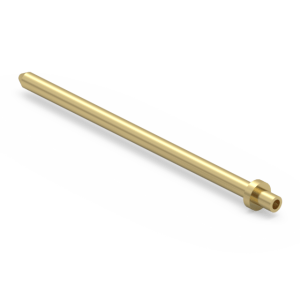
To guarantee flawless mechanical fixation, our Senior NPI Engineering Team audits each customer PCB constraint. Therefore, we eliminate soldering defects through customizable plating specifications, including matte tin over nickel for standard transmission and thick gold for high-current requirements. Sub-millimeter mechanical tolerances are fully secured before mass production, allowing for low-profile modular stacking or longer pins to bridge tall components. To initiate a pull-out strength evaluation, select the engineering queue below for immediate allocation.
Technical Specifications and Performance Matrix
| Engineering Parameter |
Verified Performance Capability |
| Base Shell Material & Process |
CNC Machined Brass Alloy with specialized annealing heat treatment |
| Standard Diameters |
0.040″ and 0.062″ options available for wire-to-board anchoring |
| Matte Tin over Nickel Plating |
Provides reliable solderability for standard power and signal transmission |
| Gold or Specialty Plating |
Maximum corrosion resistance for high-current or harsh environments |
| Mechanical Fixation |
Mechanically locked swaging process for superior pull-out strength |
Request Engineering Drawings & Custom Technical Support
For specialized pin geometries or rapid validation cycles, procurement teams can seamlessly connect with our technical desk. We enforce a strict 12-hour fast response SLA, guaranteeing the delivery of fully matched, production-ready PDF drawings upon request. To secure your position in our technical validation pipeline and share your custom swage parameters: Request Engineering Support
Disclaimer: Our mechanical footprint-matched swage terminal pins share identical PCB mounting geometry with reference legacy layouts. Outer dimensions, specific metallurgical heat treatments, and contact plating thickness can be tailored per your project budget and reliability requirements, and may differ from original OEM specifications.