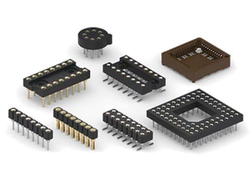
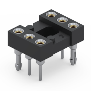
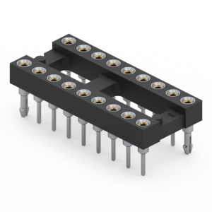
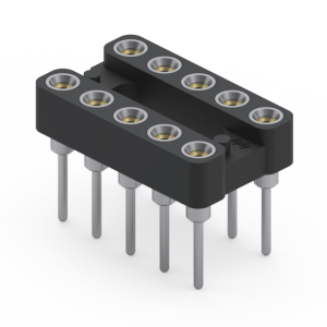
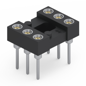
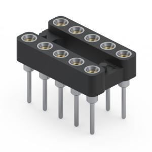
While standard stamped-pin connectors frequently risk contact fatigue and oxidation, Jiatel engineers High-Reliability Machined IC Sockets and Terminal Headers designed for mission-critical board-level deployment. Operating as a direct IC connectors factory since 2013, we deliver 1:1 footprint equivalents compatible with legacy Mill-Max 101 and 111 series configurations, ensuring flawless drop-in integration during your NPI validation and mass production scaling phases.
Engineered for Gas-Tight Signal Integrity
Our turned-pin interconnect architectures are precision-machined to withstand high-vibration, high-shock, and corrosive industrial environments.
- Multi-Finger BeCu Inner Contacts: Every socket matrix features heavy-duty 4-finger or 6-finger Beryllium Copper (BeCu) inner clips. This architecture exerts constant, controlled retention force to maintain ultralow contact resistance (< 20 mΩ) and guarantee zero signal drop-out.
- Advanced SMT Reflow Compatibility: Molded from glass-filled, high-temperature thermoplastics (PPS or PBT conforming to UL 94V-0), our entire socket assembly profile is fully optimized for lead-free reflow soldering thermal processing.
- Gas-Tight Interconnect Seals: The mechanical union between the precision-turned outer shell and the BeCu insert creates an airtight barrier, permanently protecting delicate IC leads from atmospheric corrosion.
Full-Spectrum Manufacturing Lineups
- Machined DIP & PLCC Sockets: Available from 6 to 64 positions on standard 2.54mm (.100″) and 2.00mm pitches, optimized for field-replaceable IC blocks and ruggedized burn-in testing applications.
- Precision IC Socket Terminal Headers: Turned-pin male/female mating headers engineered for multi-board stacking, sensor array interfaces, and modular device linking.
- Custom Plating & Pin Geometries: We control selective plating parameters in-house, offering configurations from cost-effective Gold Flash/Tin combinations up to 30μ” heavy hard gold plating to match your specific DFM constraints and engineering budgets.
Cross-Reference & Quality Validation Matrix
| Electrical & Mechanical Parameter |
Factory Standard Specification |
| Mating Durability |
500+ Mating Cycles (Verified via Machined Pin Lifespan Testing) |
| Current Rating |
1A to 3A per Pin (Controlled Temperature Rise) |
| Pitch Availability |
2.54mm, 2.00mm, 1.27mm (Standard & Custom Inter-Row Spacing) |
| Operating Temperature Range |
-55°C to +125°C (Extreme Thermal Environment Performance) |
Strict Tolerance Controls & Engineering Support
Precision board-to-board stacking requires tight dimensional hold to guarantee parallel pin coplanarity. We strictly prohibit the distribution of unverified digital mockups. Instead, our deployment process pivots entirely toward rigorous tolerance verification based on official [Technical Datasheets] and verified [2D Footprint Specs].
To ensure absolute mechanical compliance with your PCB layout constraints, our Senior NPI Engineering Team stands ready to audit your engineering file parameters. We strictly adhere to our 12-hour fast response SLA, providing fully matched, production-ready PDF validation drawings within 12 hours of your submission. Route your custom footprint stack-up height, pitch requirements, or selective plating criteria directly to our NPI engineering queue to lock in your project timeline.